What You Can Do with 3D Stamps†
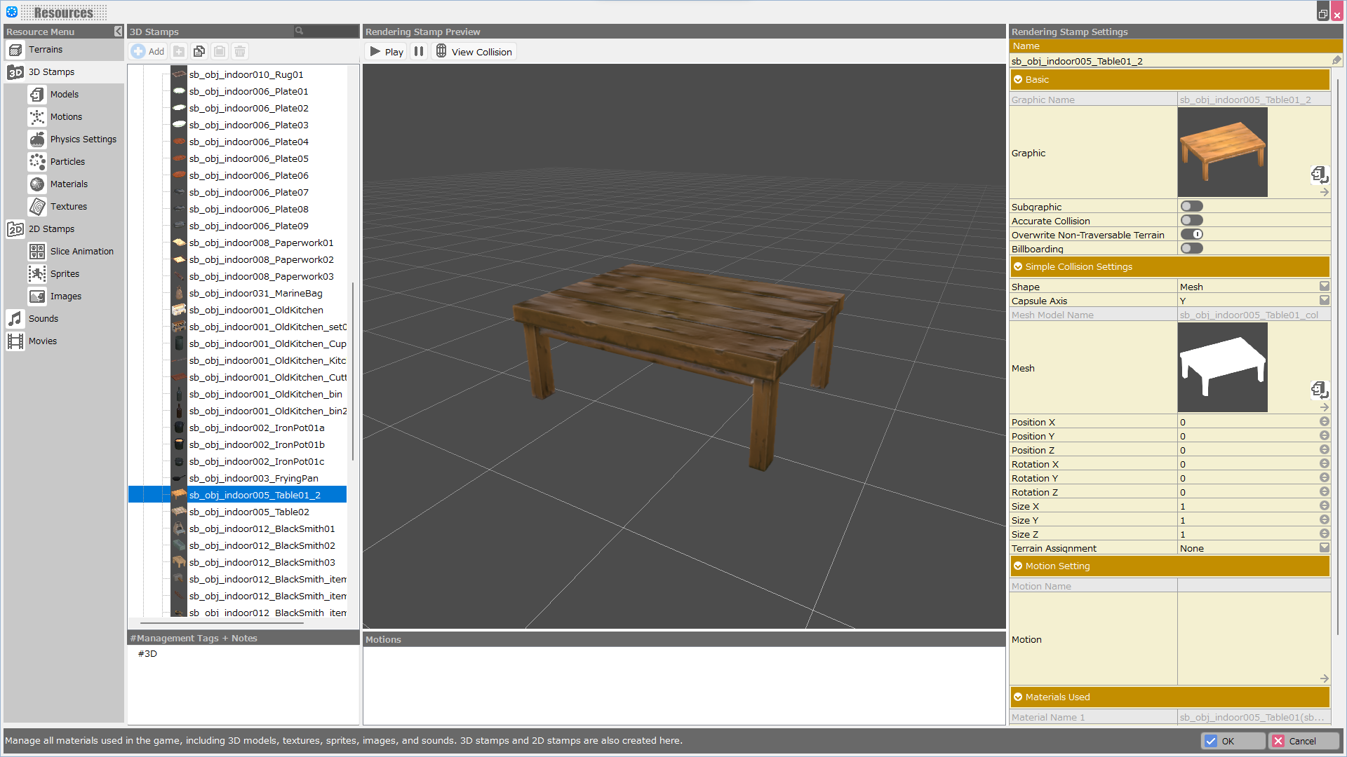
3D Stamps in the Resource Management specifies collision, motion, and material settings for the model to be used.
3D Stamp Setting Options†
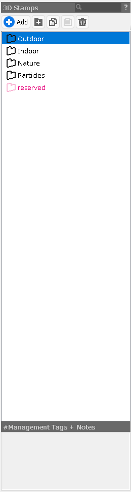
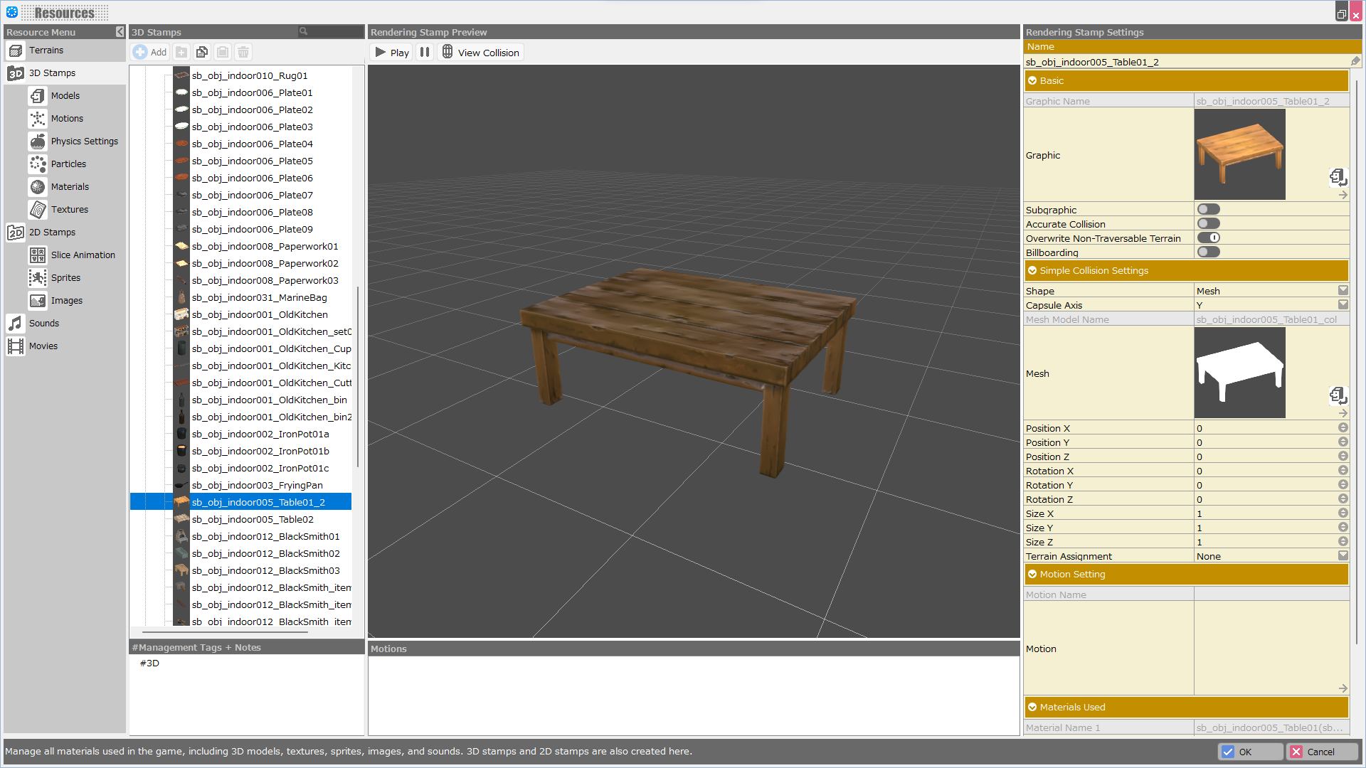
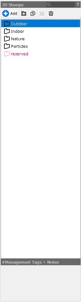
3D Stamps List
This is a list of registered 3D stamps.
The stamps registered in this list will be reflected in the stamp list in the Map Editor.
- Add Button
Add data (models, 2D images, particles, etc.) and register them as stamps.
- Folder Button
Add a folder to manage stamps.
Multiple selected stamps can be grouped into a folder, and stamps can be moved by drag & drop after adding a folder.
- Copy Button
Copy the selected stamp.
- Paste Button
Paste the selected stamp.
- Trash Button
Delete the selected stamp.
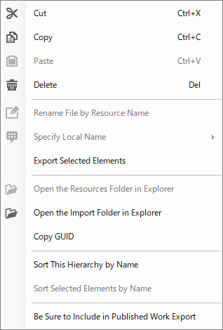
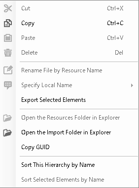
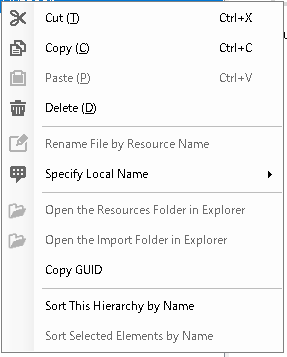
3D Stamps List / Right-Click Menu†
Right-click in the 3D Stamps list to view.
- Cut
Cut the selected stamps.
- Copy
Copy the selected stamps.
- Paste
Paste the cut and copied stamps.
- Delete
Delete the selected stamps.
- Rename File by Resource Name
Not used for 3D Stamps in the Resources.
- Specify Local Name
Folder name localization function.
English folder names can be specified when opening in the English version.
- Export Selected Elements
Export the selected elements as an .exrbr file. If multiple selections are made, they are combined into one file.
The .exrbr file is a file format that allows various resources to be compiled and imported into Bakin.
- Open the Resources Folder in Explorer
Not used for 3D Stamps in the Resources.
- Open the Import Folder in Explorer
Not used for 3D Stamps in the Resources.
- Copy GUID
Copy the GUID of the specific stamp.
- Sort This Hierarchy by Name
Sort alphabetically by name within the selected hierarchy/folder.
- Sort Selected Elements by Name
Sort only on multiple selections.
- Be Sure to Include in Published Work Export
Ensure that the selected resources are included in the work when it is exported as a published work.
(!)When exporting a work as a published work, resources other than “resources used in the game,” such as those placed on maps or used in events, will not be included in the work.
Therefore, resources that are used only by plug-ins installed in the work must be explicitly included in the work with this feature.
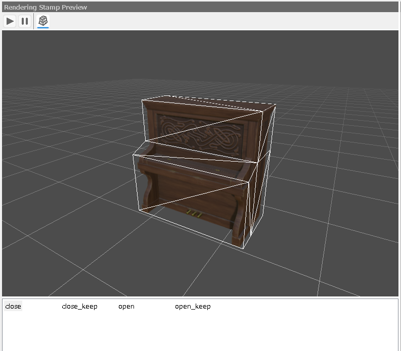
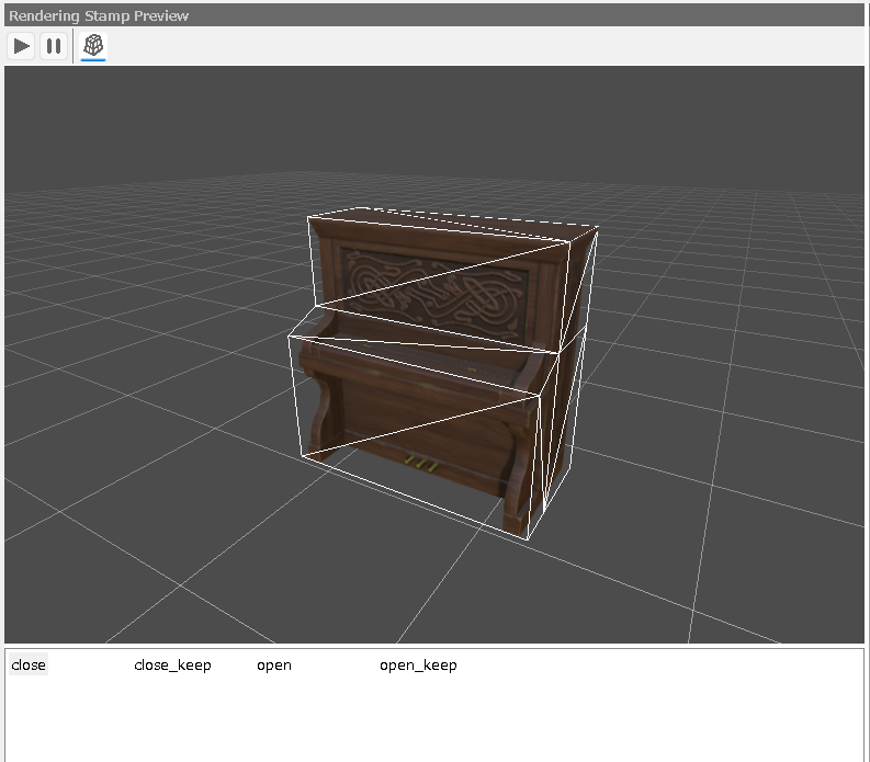
Stamp Preview†
This is a preview screen of the stamp.
Check the appearance of the model when it is placed on the map and check the collision and motion.
- Playback Button
A model with motion also plays back motions.
- Pause Button
Stop motion playback.
- Collision Display Button
Turn on/off the display of collisions indicated by white lines.
- Preview
The camera can be rotated and moved by dragging the right mouse button and shifted horizontally by dragging the middle mouse button.
- Motion List
This is a list of registered motions.
Click on a motion name to play that motion.
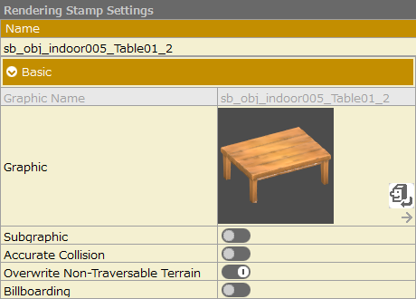
Rendering Stamp Settings†
This section provides detailed settings for the stamp.
- Name
Specify a name for the stamp.
(You can also change it by clicking twice on the stamp name in the 3D stamp list.)
- Copy Button
Copy the contents of “Rendering Stamps Settings”.
(!)Subgraphic information will not be copied.
- Paste Button
Paste the contents of the copied “Rendering Stamps Settings”.
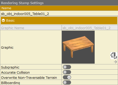
- Basic
- Graphic Name
The name of the model specified.
- Graphic
Click to select a model to be set as the stamp graphic.
The jump button can also be used to go to the setting screen for the currently set data.
- Subgraphic
Other graphics can be registered as Subgraphic.
- Accurate Collision
When off, "Simple Collision Setting" is enabled.
When "On" is selected, "Accurate Collision Setting" is enabled. The physical settings registered in Physical Settings Management can be selected.
- Overwrite Non-Traversable Terrain
If this stamp is placed on top of terrain specified as "Non-Traversable", the character will be able to progress over it.
- Billboarding
Turning it on will cause the stamp to change direction only in response to the camera's Y-axis orientation.
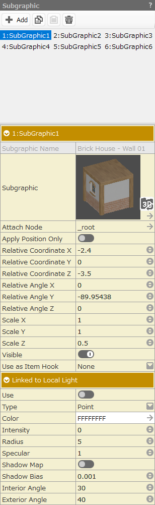
Subgraphic†
Subgraphic is a feature that allows other stamps to be attached to a stamp and used as a single stamp.
Turn on the stamp's property “Subgraphic” to register subgraphics.
Add a new subgraphic with the Add button and select the graphic you wish to register under “Subgraphic”.
You can reflect changes in settings at once by changing property entries while multiple subgraphics are selected on the list.
- Subgraphic Properties
- Subgraphic Name
The name of the stamp specified as a subgraphic.
- Subgraphic
Click to select a stamp to be set as a subgraphic.
The jump button can also be used to go to the setting screen for the currently set data.
- Attach Node
Specify the model or bone to be used.
- Apply Position Only
When turned on, does not use bone orientation, only bone position.
This is especially useful when using particles as subgraphics, since the rotation XYZ of the subgraphic is fixed even if the parent graphic is rotated.
- Relative Coordinate X, Relative Coordinate Y, Relative Coordinate Z
You can set the relative position of the subgraphic stamp to the parent stamp.
- Relative Angle X, Relative Angle Y, Relative Angle Z
You can set the angle of the subgraphic stamp relative to the parent stamp.
- Scale X, Scale Y, Scale Z
You can set the scale of the subgraphic.
- Linked to Local Light
This is the setting for attaching local lights (point lights) as subgraphics.
It is also possible to set only local lights without specifying subgraphic stamps.
For example, it can be used in a first-person dungeon RPG to generate light from the main character.
- Use
Apply a local light as a subgraphic.
- Color
Set the color of the local light.
- Intensity
Set the intensity of the local light.
- Radius
Set the applying radius of the local light.
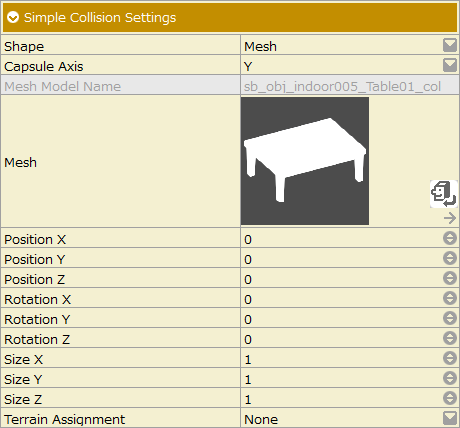
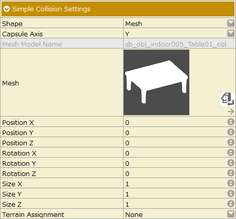
Simple Collision Settings†
- Shape
- [Box]
Specify the collision of a box shape.
- [Sphere]
Specify the collision of a sphere.
- [Capsule]
Specify the collision of a capsule type.
- [Mesh]
You can specify the mesh collision you have prepared.
- [Vehicle]
Collision can be specified for a vehicle.
- Capsule Axis
Specify the direction of the axis for capsule collision setting.
- Mesh Model Name
The model name of the Mesh collision specified in the mesh.
- Mesh
Click to select the model to be set as the Mesh collision for this stamp.
The jump button can also be used to go to the setting screen for the currently set data.
- Position XYZ
Specify the position XYZ of the collision model, respectively.
- Rotation YYZ
Specify the rotation values XYZ for the collision model, respectively.
- Size XYZ
Specify the size XYZ of the collision model, respectively.
- Terrain Assignment
You can specify a "terrain" and add the "sound effects" and ""state" changes when walking on the terrain" to this stamp.
This setting is valid even when this stamp is used with the event's graphic.
You can edit the information set for "Terrain" in Resources > Terrains.
The "sound effect" will be the "footsteps" when the player walks on this stamp.
By taking advantage of the "change in 'status' granted when walking on the stamp," the player cast(s) can be "poisoned" when walking on this stamp, and so on.
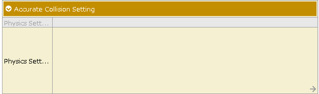
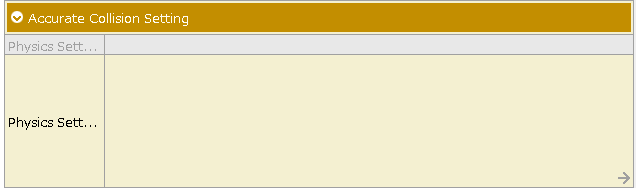
Accurate Collision Setting†
Select this option if you wish to add complex physics settings such as motion-synchronized collisions for door models, etc.
You must prepare your physics settings in advance in the Physics Settings Management screen.
- Physics Setting Name
The name of the physics setting you have specified in the Physics Settings.
- Physics Setting
Click to select the “Physics Settings” for this stamp.
The jump button can also be used to go to the setting screen for the currently set data.
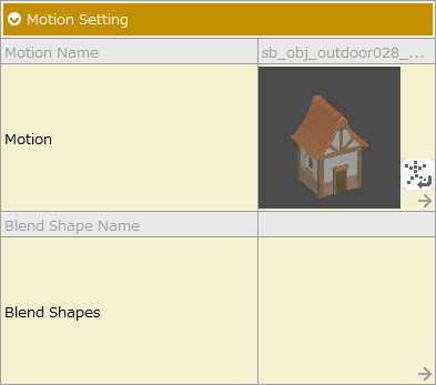
Motion Setting†
Select the motion you added on the motion management screen.
The motion must be specified in the motion management screen in advance.
- Motion Name
The name of the selected motion specification.
- Motion
Click to select the motion to be set for this stamp.
The jump button can also be used to go to the setting screen for the currently set data.
- Blend Shape Name
The name of the brand shape you set.
- Blend Shapes
Click to select a blend shape to be set for this stamp.
The jump button can also be used to go to the setting screen for the currently set data.
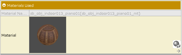
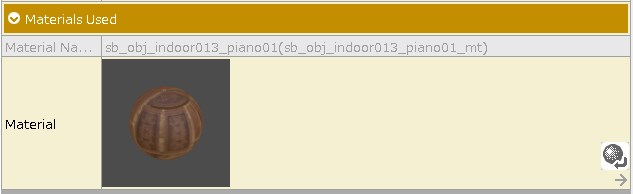
Materials Used†
Lists the materials used in the model registered in the graphic.
By changing the material used, it is possible to change only the material without changing the model.
- Material Name
The name of the material being specified.
- Material
Click to select the material to be set for this stamp.
The jump button can also be used to go to the setting screen for the currently set data.
![[PukiWiki]](./skin/BAKIN_logo_92.png "[PukiWiki]")
 Resouces_3DStamps_Subgraphic.png 100 download
[Information]
Resouces_3DStamps_Subgraphic.png 100 download
[Information]
 Resouces_3DStamps_MotionSettings.png 110 download
[Information]
Resouces_3DStamps_MotionSettings.png 110 download
[Information]
 Resouces_3DStamps.png 71 download
[Information]
Resouces_3DStamps.png 71 download
[Information]
 Resouces_3DStamps_Basic.png 91 download
[Information]
Resouces_3DStamps_Basic.png 91 download
[Information]
 Resouces_3DStamps_SimpleCollisionSettings.png 291 download
[Information]
Resouces_3DStamps_SimpleCollisionSettings.png 291 download
[Information]
 Right.png 319 download
[Information]
Right.png 319 download
[Information]
 Stamp Preview.png 358 download
[Information]
Stamp Preview.png 358 download
[Information]
 Accurate Collision Setting.png 307 download
[Information]
Accurate Collision Setting.png 307 download
[Information]
 Materials Used.png 353 download
[Information]
Materials Used.png 353 download
[Information]
 3DStamp Shape.png 173 download
[Information]
3DStamp Shape.png 173 download
[Information]
 3D Stamps List Right.png 257 download
[Information]
3D Stamps List Right.png 257 download
[Information]
 3D Stamps List.png 316 download
[Information]
3D Stamps List.png 316 download
[Information]


